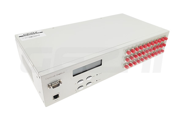
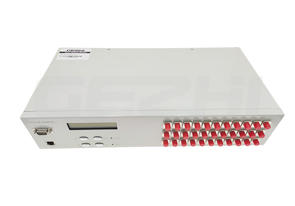
GEZHI multi channel Fiber optical switch features fast switching time with large core fiber as S105/125um, S200/240um, S272/300um, S365/400um, S550/600um or customized fiber. The operating wavelength can support 280nm, 375nm, 405nm, 488nm, 525nm, 532nm, 650nm, 780nm, 850nm, 980nm and other customized wavelength. This optical switch is a kind of light path control equipment,can realize multi-channel fiber optic light path switching,In optical fiber transmission system, it is used for multi-channel fiber monitoring, multi light source/ detector selection, and optical fiber path protection etc. Besides, it is also used in optical fiber test system for optical fiber and its component test, outdoor cable test and multi-port optical sensors monitoring system.
Technical Index
Parameter | Unit | 1x4 | 1x8 | 1x12 | 1x16 | 1x24 | 1x32 | 1x64 | 1x128 |
Wavelength Range | nm | 280nm, 375nm, 405nm, 488nm, 525nm or 532~1064 nm and Customized | |||||||
Testing Wavelength | nm | 280nm, 375nm, 405nm, 488nm, 525nm or 532/650/780/850/980nm | |||||||
Insertion Loss (Max) | dB | ≤0.8 | ≤0.8 | ≤1.0 | ≤1.5 | ≤1.5 | ≤1.5 | ≤1.8 | ≤2.0 |
Return Loss | dB | SM ≥ 50 | |||||||
Crosstalk | dB | ≤-70 | |||||||
PDL | dB | ≤0.05 | |||||||
WDL | dB | ≤0.20 | |||||||
TDL | dB | ≤0.20 | |||||||
Repeatability | dB | ≤0.02 | |||||||
Lifetime | times | >107 | |||||||
Switching Time | ms | ≤10 (Adjacent Channel) | |||||||
Optical Power | mW | ≤500 | |||||||
Control Mode | / | TTL or Customized | |||||||
Operating Temperature | ℃ | -10~+55 | |||||||
Storage Temperature | ℃ | -40~+85 | |||||||
Ordering Information OSW-XxX-X-XX-X-XX-XX-XX-XX
OSW | Mode | Wavelength | Package | Fiber Type | Fiber Diameter | Fiber Length | Connector |
1x4 1x8 1x16 1x32 1x64 1x128 S=Specity | S=SM M=MM | 280=280nm 375=375nm 405=405nm 488=488nm 532=532nm 650=650nm 780=780nm 850=850nm S=Specify | B=Metal Box R=Rackmount S=Specify | S105/125 S200/240 S272/300 S365/400 S550/600 S=Specify | 09=900um 20=2.0mm cable 30=3.0mm cable S=Specify | 05=0.5m 10=1.0m S=Specify | 00=None FP=FC/UPC FA=FC/APC SP=SC/UPC SA=SC/APC LP=LC/UPC LA=LC/APC S=Specify |
PIN Configurations
DB-9 male connector (1xN≤16)
DB-9 male connector | |||
Pin No. | I / O | Signal | Description |
1 | Input | D0 |
D0~ D3 is channel selection Bit0~Bit3,D0 is low, D3 is high |
2 | Input | D1 | |
3 | Input | D2 | |
4 | Input | D3 | |
5 | Input | RESET | TTL, Low level reset to channel 0. High level means channel selection bits are effective. |
6 | Out | READY | TTL, Ready (High=Not ready, Low=Ready) |
7 | Out | ERROR | TTL, Error OR Failure , (High=Error, Low=No error) |
8 | Power | GND | Ground |
9 | Power | VCC | 5.0±5% VDC Power Supply (max 500mA) |
DB-15 male connector (1xN≤128)
DB-15 male connector | |||
Pin No. | I / O | Signal | Description |
2 | Input | D0 |
D0~ D5is channel selection Bit0~Bit4,D0 is low, D4 is high |
3 | Input | D1 | |
4 | Input | D2 | |
5 | Input | D3 | |
6 | Input | D4 | |
10 | Input | D5 | |
11 | Input | RESET | TTL, Low level reset to channel 0. High level means channel selection bits are effective. |
7 | Out | READY | TTL, Ready (High=Not ready, Low=Ready) |
8 | Out | ERROR | TTL, Error OR Failure , (High=Error, Low=No error) |
1,9 | Power | GND | Ground |
12 | Power | VCC1 | 5.0V±5% VDC motor power (max 950mA) |
15 | Power | VCC2 | 5.0V±5% VDC Drive circuit power(50mA) |
13,14 | NC | NC | |
Control Chart

Timing Diagram:

Channel Selection Table:
Channel | D0 | D1 | D2 | D3 | D4 | D5 | RESET |
COM-0 | x | x | x | x | x | x | 0 |
COM-1 | 0 | 0 | 0 | 0 | 0 | 0 | 1 |
COM-2 | 1 | 0 | 0 | 0 | 0 | 0 | 1 |
COM-3 | 0 | 1 | 0 | 0 | 0 | 0 | 1 |
... | 1 | ||||||
COM-126 | 1 | 0 | 1 | 1 | 1 | 1 | 1 |
COM-127 | 0 | 1 | 1 | 1 | 1 | 1 | 1 |
COM-128 | 1 | 1 | 1 | 1 | 1 | 1 | 1 |
Address : 5F,Zhongshunyiquan Industry Park, Fuqian Road,Longhua District, Shenzhen, China
Address : 5F,Zhongshunyiquan Industry Park, Fuqian Road,Longhua District, Shenzhen, China
Tel : +86-755-23771707
Whatsapp : +86 13544277727
Email : sales@gezhi.net
Skype : 13544277727
Copyright Gezhi Photonics Co.,Ltd. All rights reserved.